Tail rotor
The start
The humble beginning of my helicopter journey started with building the tail rotor. The plans I received consisted of a set of printed PDFs detailing several parts:
Tail rotor
Main rotor
Swash plate
Frame and drive system
Control systems (if memory serves me right)
You might wonder, “If you have the plans, why not double-check while writing this?” The plans are safely tucked away in my desk drawer, stored in the envelope they came in. I’ve opened that drawer hundreds of times to review them. Most of the sheets are now stained and smudged from handling them with dirty hands during machining and welding sessions.
Pro tip: Make copies of your plans and keep the originals pristine!
So, why didn’t I check the “control systems” section? Simply because I couldn’t find a dedicated plan for it. That said, I must have had some reference since I managed to build the parts!
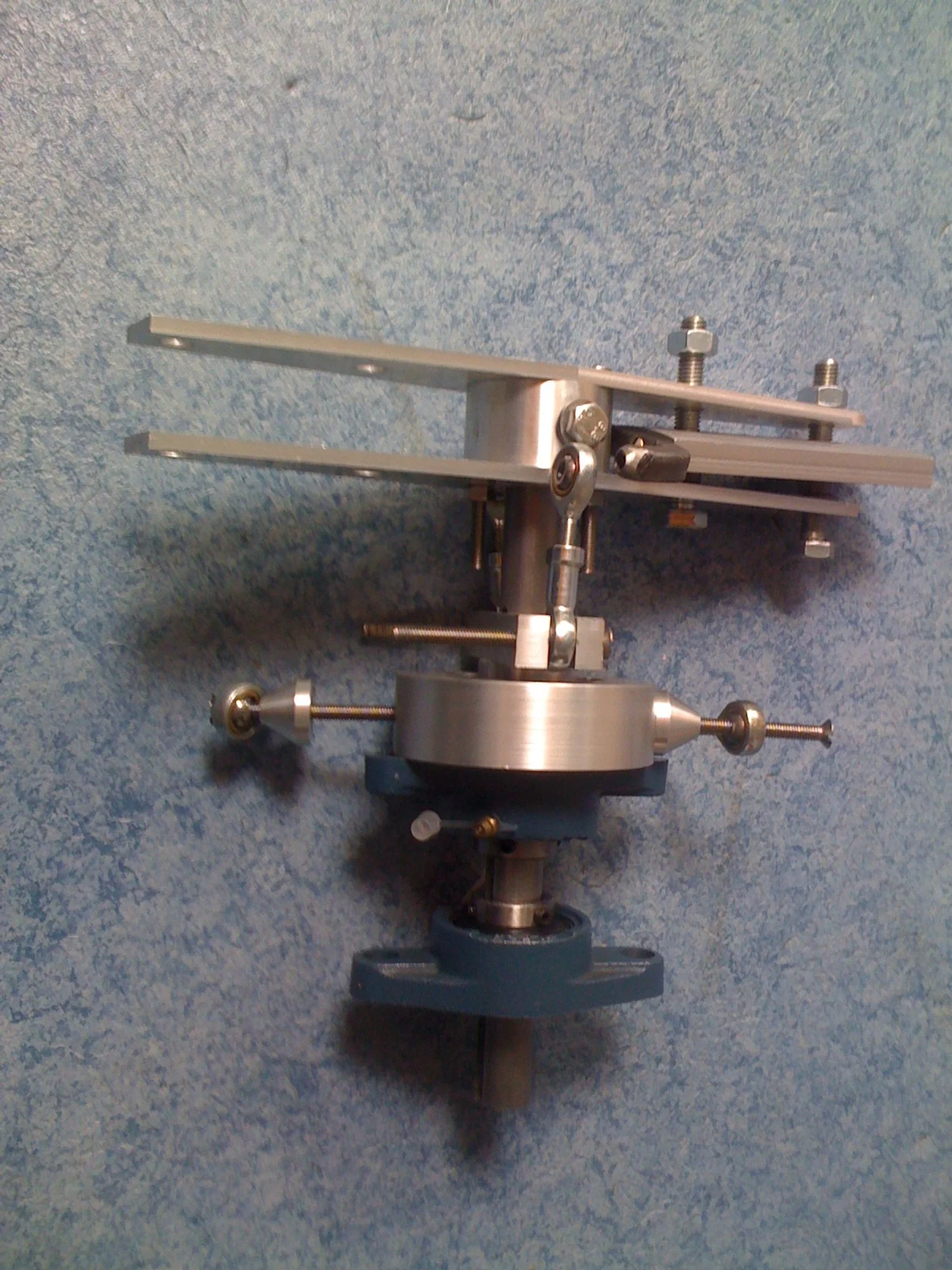
The hub
The hub design is surprisingly straightforward. It consists of an aluminum bushing with a set of holes drilled through it. Two plates are bolted onto this bushing, with the tail rotor blades fitting snugly between the plates. The design is ingenious—the tail rotor blades are tethered, with the hinging mechanism embedded inside the blades using two ball joints or "tail rotor feathering bearings."
Machining these parts was within my capabilities, but I distinctly remember struggling with the hole pattern. At the time, I didn’t own a rotary table for my milling machine. My solution was to measure precisely, use a center punch, and drill the holes in all the parts while clamped and stacked together. It worked surprisingly well.
When I finished the hub, I recall my father asking, “What are you building?”
“A helicopter,” I replied.
“A small one this time?” he replied.
“Nope. This is just the hub for the tail rotor.”
Following the Plans?
The plans specified ⅜-inch thick plates—roughly 3mm but precisely 3.175mm. After a year of studying aerospace engineering, I understood the importance of tight tolerances in aerospace design. So, could I round down to 3mm?
The metric system posed a challenge. Materials with imperial dimensions aren’t readily available in the Netherlands. I could buy 4mm sheets and machine them to spec, but doing that for every part would be time-consuming. For most parts, I decided to round up. For tubing in the frame, I calculated strength and stiffness to find suitable substitutes. However, my tendency to round up led to a helicopter with a bit of obesitas (extra weight).
I’m aware of the snowball effect: higher weight means more lift is required, leading to higher power and torque demands, larger loads, and stronger materials. Fortunately, I ran some calculations on the drivetrain, and it should handle the increased loads.
But what about the tail rotor plates? Should I use 3mm or 4mm? If you’ve ever held plates of those dimensions in your hands, you’ll know they feel flimsy—easily bendable. Trusting my instincts, I opted for 6mm plates. While it’s heavier, I felt more confident in their rigidity and strength.

The first impossible part
When faced with the first seemingly impossible part, I couldn’t help but feel a mix of frustration and determination. Here I was, equipped with a brand-new milling machine, a proper machine clamp, a nice set of end mills, and clamping tools—basically, all the machinery I thought I’d ever need. Yet, I found myself struggling with what seemed like a simple task: shaping an aluminum block into the front section of a NACA0012 airfoil.
The challenge? My milling machine is a two-axis setup, and neither axis operates in curves or inclines—it’s strictly straight cuts only. My first thought: “I need a CNC machine.” Years later, I finally built a small CNC setup, but at the time, I had to rely on creativity and manual techniques to solve the problem.
The Workaround
I started by sketching the airfoil contour on the side of the aluminum block and clamping it securely. Using the mill, I carefully machined away as much material as possible in a staircase pattern. Each pass brought me closer to the final shape, though it was far from smooth or finished at this stage.
To refine the contours, I turned to my trusty belt sander. It was slow, tedious work—pressing the block against the sander to smooth out the steps left by the milling process. The aluminum heated up quickly, and I burned my hands a couple of times before learning to keep a bucket of water nearby for cooling the part between sanding sessions.


The blades
This step was when I realized something important: I had purchased a set of plans, not a builder’s manual. While the plans included all the necessary parts and most dimensions were precise, there were no instructions on how to actually fabricate certain components. Case in point: bending a sheet of aluminum into a NACA0012 airfoil.
The plans didn’t specify the size of the plate required for the blade. Sure, I could calculate or estimate the circumference, but the bending process itself presented a whole new set of challenges.
SHaping the Airfoil
To get started, I shaped a piece of wood into a profile similar to the desired aluminum airfoil—only longer. I stuck to using the belt sander for this, as I wasn’t keen on coating my milling machine in wood dust. This wooden form became the guide for bending a thin sheet of aluminum into the blade’s airfoil shape.
Of course, there was springback, and the resulting shape was probably not an exact NACA0012. But my primary goal wasn’t perfection—it was consistency. I needed two blades as similar as possible to ensure they’d stay balanced in flight.
Bending the Trailing Edge
The trailing edge was bent back by sandwiching the blade between two wooden blocks, clamping it tightly, and carefully wiggling the blade back and forth. It wasn’t a fatigue test—just enough movement to get the job done.
The flat area near the trailing edge, intended for riveting, presented its own issues. Springback prevented the edges from lying flush against each other. My solution? Temporary gluing. I initially tried super glue, thinking the bond area was large enough to resist the minimal force from springback. After waiting an hour (even though the glue promises to dry in seconds), I released the clamps—and the trailing edge promptly sprung back open.
Super glue has never been my friend, it seems to only work as advertised on my finger. On the second attempt, I cleaned, sanded, cleaned again, and used epoxy instead. This time, the bond held. While the epoxy alone may have sufficed, I added rivets for good measure.
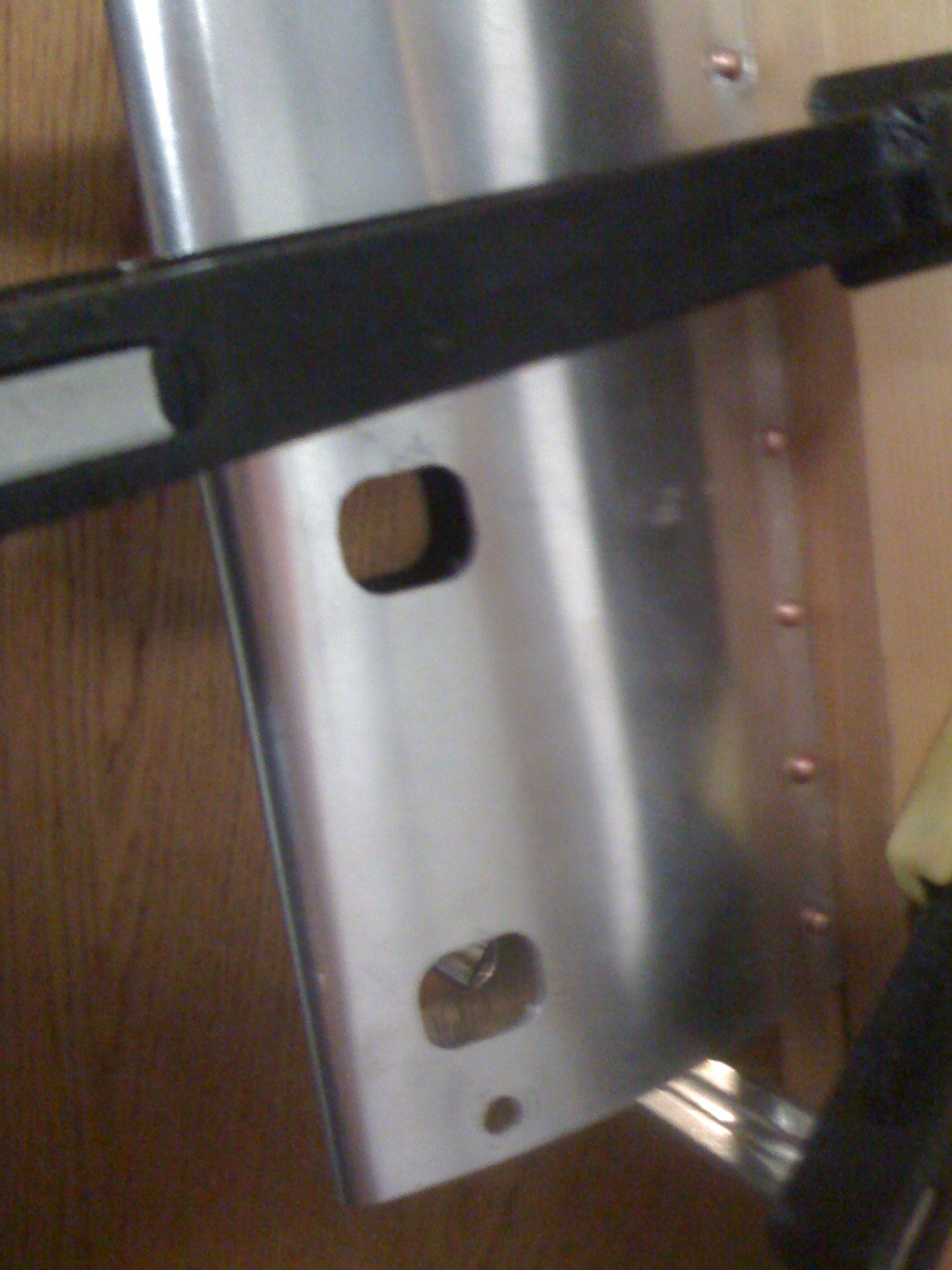
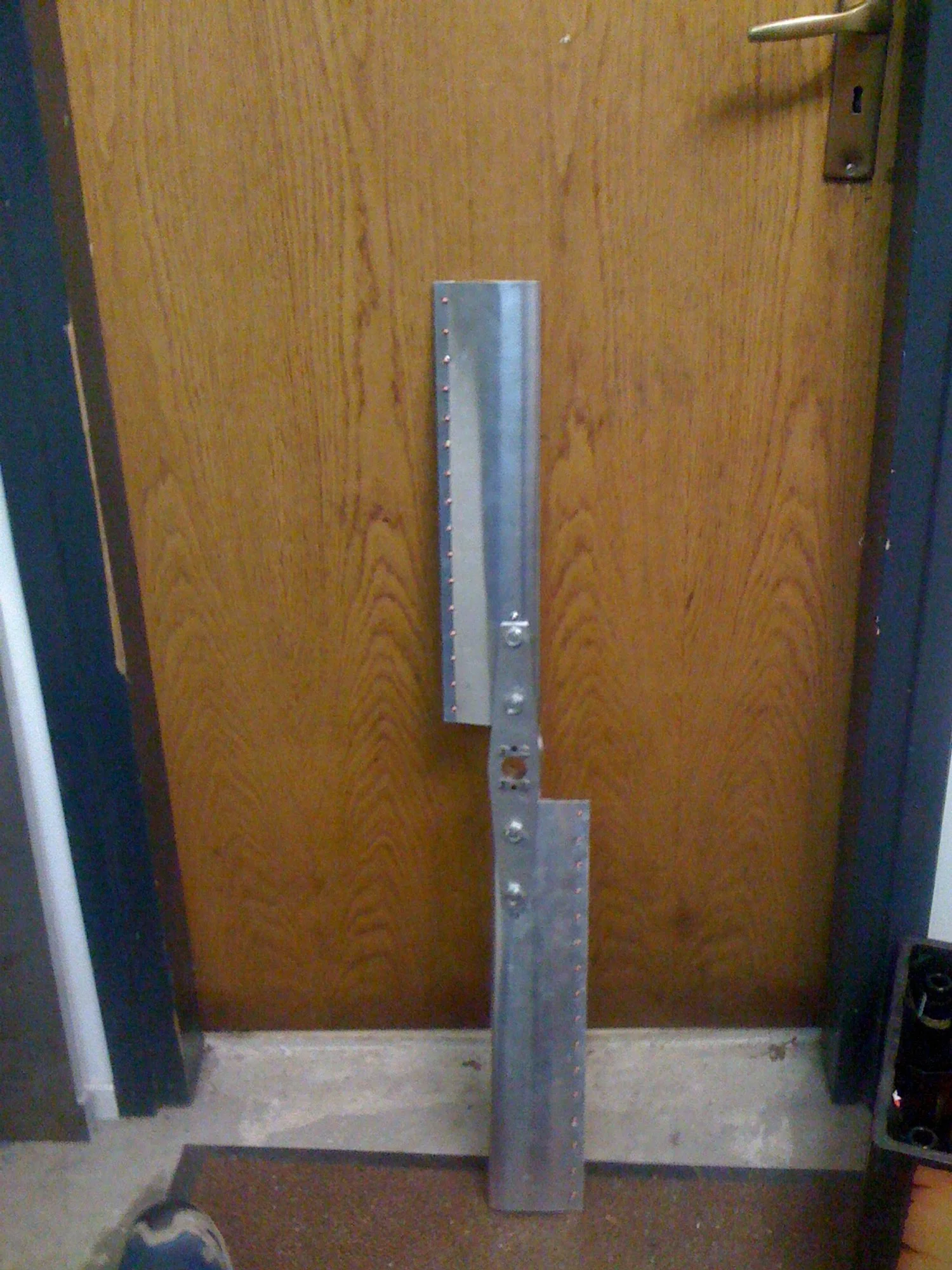
Riveting the Trailing Edge
Using solid rivets was a first for me. While I was familiar with blind rivets, solid rivets reminded me of grand, old engineering marvels like the Eiffel Tower. As it turns out, they’re great for aerospace applications too—no worrying about nuts vibrating loose, and they look fantastic.
Without a proper rivet gun or tools for solid rivets, I improvised. I built a small tool to press the rivets into shape using my vice, and the result turned out surprisingly well.
Final Touches
After bending, the trailing edges didn’t align perfectly. To address this, I trimmed them on the milling machine to make them nice and flat. Clamping the blades for trimming was another challenge, but the wooden form I’d initially created came to the rescue. I used it to support the blade during both the trimming process and when cutting the slots for the tethering bolts.
The remaining parts presented challenges primarily due to the large size of the aluminum blocks that needed to fit into my lathe. While the machining itself was relatively straightforward, handling such sizeable components is always a challenge on a smaller sized lathe. Most of these parts included the tail rotor swash plate and drive shaft, which you can see in the final image.