Swash Plate
Function
The swash plate of the AW95 helicopter still fits neatly in my desk drawer. Despite its compact size, it was one of the more complex parts to build and serves a critical function. The swash plate transfers the pilot's control inputs—both cyclic and collective—directly to the rotor blades. This mechanism enables the helicopter to manipulate the rotor disk’s thrust vector, crucial for steering and overall maneuverability.
Its operation goes beyond simply increasing or decreasing thrust (collective control). The cyclic control allows the pilot to adjust the thrust vector's direction, enabling the helicopter to move forward, backward, and sideways. This is achieved by varying the blade pitch at specific angular locations around the rotor disk. Even slight pitch differences can tilt the entire rotor disk, redirecting the thrust vector as needed.
Understanding this process can be counterintuitive, primarily due to the rotor disk dynamics, including a 90-degree phase difference between pitch input and rotor disk response. For those new to the topic, several excellent videos explain how helicopters fly, including these unique dynamics.
Building the Swash Plate
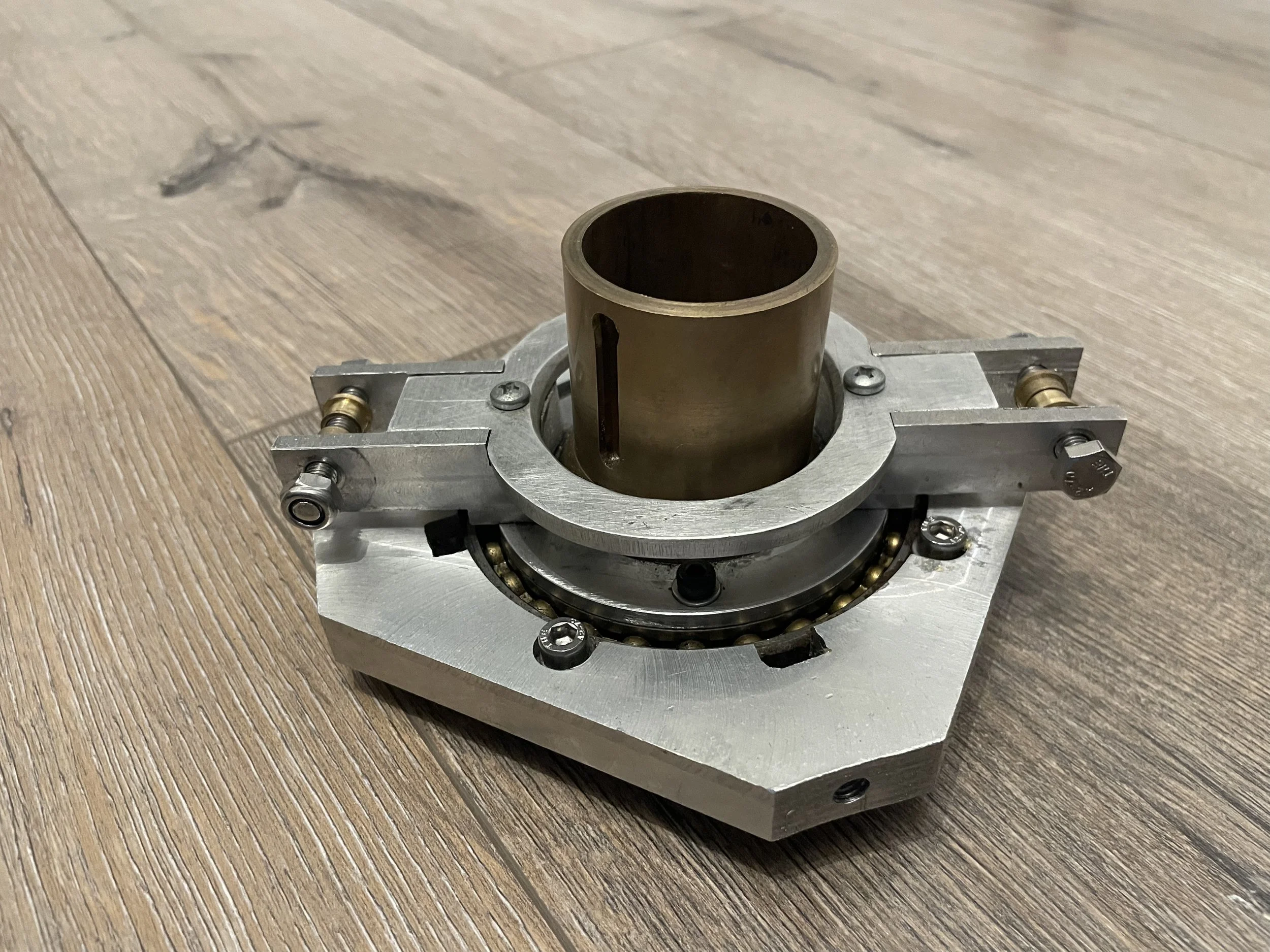
The swash plate itself was a relatively straightforward build—likely why I don’t have many photos documenting the process. The build begins with the main plate, or the 'swash plate.' This plate houses a large bearing, securely clamped in place with four bolts and nuts on its outer ring.
The swash plate also includes four key connection points:
Three control rod connections: These translate the pilot’s inputs into blade adjustments.
Anti-torque guide: A slot-and-guide system prevents the outer plate of the swash plate from twisting relative to the helicopter frame.
A Note About Bolts: Many of the bolts shown in my photos are placeholders I had on hand during the build process. For the final assembly, I replaced them with higher-quality hardware designed to meet the necessary specifications.
Although the build process was relatively simple, the precision required for these components to function reliably highlights the elegance of the design. This part plays a pivotal role in translating pilot intent into precise and controlled flight behavior.
"No Seals, You Ask?"
Yes, I knew exactly what type of bearing I needed for the swashplate. The problem? I simply couldn’t afford it. If memory serves, the sealed version cost around €250, while the unsealed one was only €50. Faced with the price gap, I opted for the unsealed bearing and decided to take extra precautions to protect it.
My plan was simple: keep the bearing covered at all times and avoid testing the helicopter in dusty or sandy environments. Since I never intended to fly the helicopter far, frequently, or for long durations, I justified the compromise as acceptable. However, for years afterward, this decision nagged at me. I was constantly checking the bearing, carefully twisting and listening for any signs that dust or dirt had infiltrated it.
Here’s some advice for anyone considering a similar project: only start building a helicopter when you can afford the right parts. Cutting corners like this can lead to endless worry and potential setbacks.
A New Swashplate Design
For this and other reasons, I eventually built a completely new swashplate. This updated version addressed multiple issues, including the challenging construction of the ball joint. Instead of fabricating a custom joint, the new design utilizes a readily available ball joint, making the build more straightforward and reliable.
I personally designed and tested this improved swashplate, and I now sell the plans for it in my webshop. For more details, check out the New Swashplate chapter on this website.


Ball Joint
A significant portion of the swash plate plans is dedicated to constructing components for the ball joint. According to the plans, the ball itself is to be sourced from a local hardware store—a tractor hitch ball, to be precise—and then bored through. The assembly is designed as a press-fit connection to a uniball sleeve, secured with Loctite.
While this approach might work, I wasn’t entirely satisfied with it. Instead, I decided to machine the entire ball joint as a single piece—a more challenging but rewarding project for the lathe. I chose brass as the material for its excellent sliding properties against steel, making it well-suited for this application. Brass also offers the necessary durability for a ball joint, and I'm sure that the forces acting on this component would not exceed its strength limitations.
Crafting the Ball Shape
Cutting a precise ball shape on a lathe requires a special tool known as a "ball-turning attachment." Unfortunately, I didn’t have one at the time, so I had to innovate. I adopted a method similar to what I used when milling the NACA0012 profile for the aluminum block:
Coordinate Mapping: I created an Excel sheet to calculate the coordinates of a circle.
Manual Profiling: Using these coordinates, I manually positioned the parting tool along the ball’s surface, accounting for the tool's width to ensure accuracy.
Rough Geometry: This process produced a ball-like shape with a stepped geometry resembling a staircase.
To achieve a smooth, final finish, I relied on good old-fashioned handwork. While the lathe was running, I filed, sanded, and polished the ball to the exact dimensions required. The result was a polished, precisely machined ball joint that I was proud to include in the swash plate assembly.


