Hexa pod
Hexapod: A Versatile Measurement Tool
A hexapod is a device consisting of two separate platforms connected by six rods. While many variations exist, the most exciting versions incorporate six linear actuators, such as hydraulic pistons, enabling dynamic motion. However, the hexapods I’m currently focusing on are static—that is, they don't move.
So, what purpose do they serve? These static hexapods are used for 6 Degrees of Freedom (DOF) measurement. Think of it as a high-tech scale, capable of measuring forces and moments in all six directions: three linear forces (X, Y, Z) and three rotational moments (pitch, roll, yaw).
This functionality allows hexapods to serve as versatile tools for experimental setups. For instance, I use hexapods to measure the reaction forces and moments generated by a brushless DC motor spinning a large propeller.
Hexapods can also be employed in wind tunnels to measure reaction forces on models mounted on them. In such contexts, they are often referred to as a "balance." While not all balances are hexapods, many variations exist, each tailored to specific applications.
By providing precise 6 DOF measurements, hexapods open up a world of possibilities for experimental research in fields like aerospace, robotics, and engineering!
First design
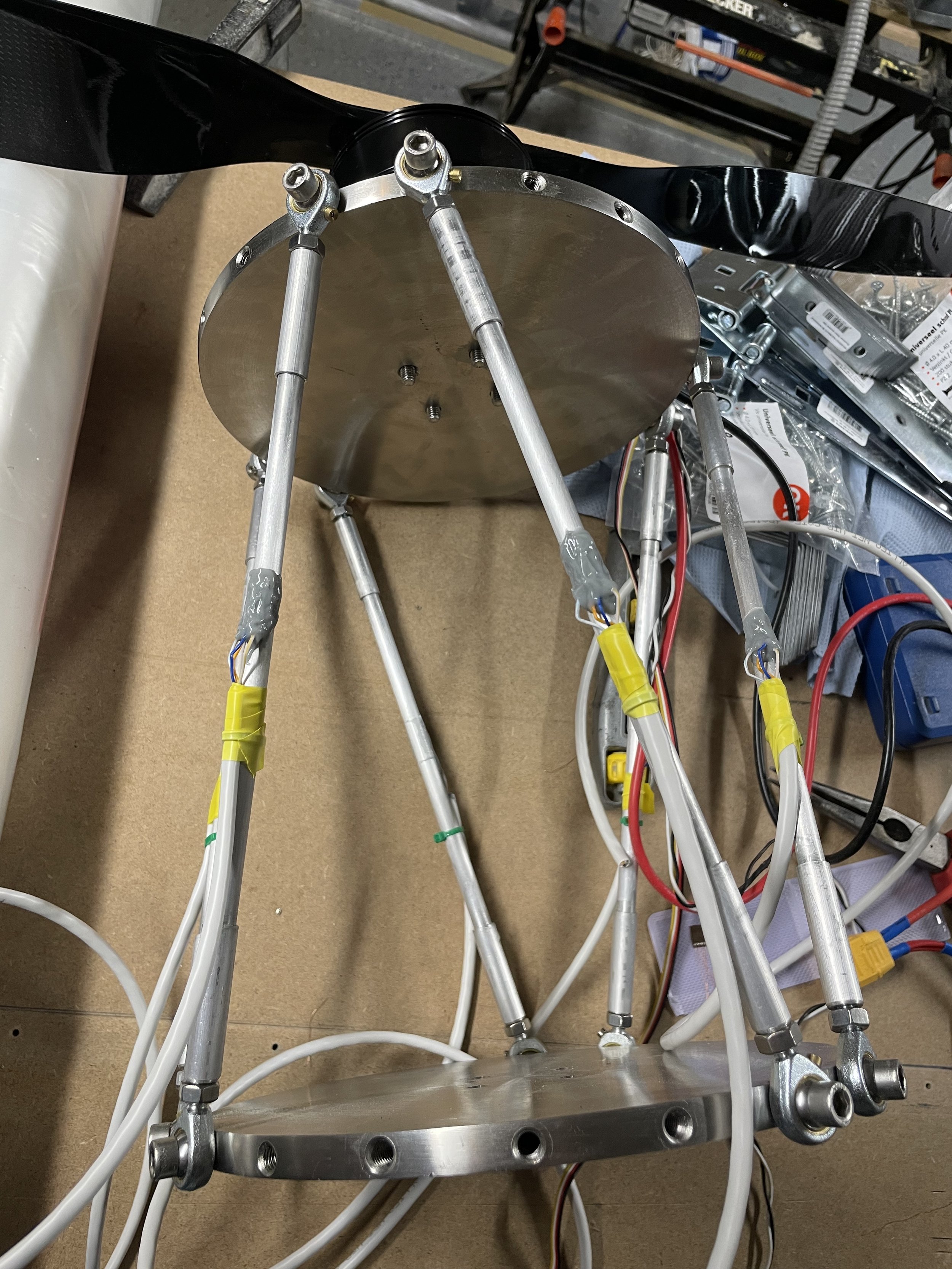
I’ve built several versions of my hexapod, and you can check out the design iterations and the brushless DC motor in action on my YouTube channel. The first version, displayed at the top of this page, features large stainless steel round plates connected by rods via rod ends. The rods are crafted from thin-walled aluminum tubing, designed to measure strain on their surface when subjected to tension or compression.
To achieve this, I mounted a strain gauge on each rod and carefully sealed it with glue. The result was remarkably sensitive load cells! Strain gauges never cease to amaze me with their sensitivity, making them fantastic tools for a large variety of experiments.
The Flaw in the Design
However, the design had a critical flaw. While the strain on the rod surfaces responds well to axial forces, the surface strain increases strongly when the rods experience even slight bending. This bending introduces errors in the measurements, as the strain caused by the bending moment overwhelms the strain from axial forces.
This issue can theoretically be mitigated by ensuring that the rods are only loaded axially (e.g., avoiding any lateral pressure). Unfortunately, friction in the rod ends introduces unwanted moments into the rods, leading to erroneous strain readings even without external lateral forces.
I spent an entire day on calibration experiments, loading the hexapod in six linearly independent ways to gather calibration data. To my dismay, there was significant hysteresis in the system. While I expected some minimal hysteresis, the reality was far worse. The rod ends, which felt almost frictionless, introduced hysteresis that rendered precise calibration nearly impossible. For example, applying a 10 kg load in the X-direction caused errors of ±2 kg in the Z-direction—far too inaccurate for my propeller measurements. The cross-sensitivity of other directions were all much smaller, quite acceptable actually. Subsequent experiments confirmed that the hysteresis was indeed due to friction inherent in the rod ends.
It’s visually impressive—sturdy, sensitive, and sleek—but it turned out to be a disappointing hexapod in practice.
Exploring Alternatives
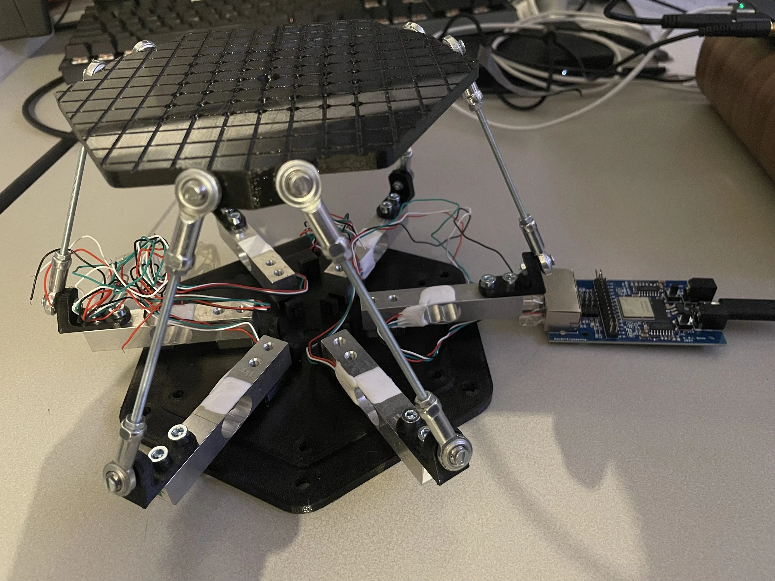
To address this, I created a 3D-printed hexapod design that relocated the load cells to the base. This setup aimed to isolate the strain gauges from the bending effects on the rods. However, the new design still suffered from hysteresis problems due to friction in the rod ends.
To investigate further, I tested the 3D-printed hexapod using two different sets of rod ends: one with noticeable friction, even when unloaded, and another with minimal friction when unloaded. Initial tests showed the following:
High-Friction Rod Ends: Significant offsets in load cell readings after wiggling, pressing, or applying torque to the platform.
Low-Friction Rod Ends: Reduced offsets when unloaded, but the problem resurfaced when a load of 1–2 kg was applied. The rod ends' friction under load reintroduced hysteresis, making precise measurements impossible.
It became clear that simply changing the placement of the load cells wasn’t enough to eliminate the issue.
This iterative process highlights the complexity of achieving accurate measurements in multi-DOF setups and reinforces the importance of addressing friction effects in future designs. The journey continues as I refine these systems to deliver the precision required for demanding applications.
Clearly, rod ends with minimal initial friction and a very low friction coefficient are critical. I have not yet tried to get my hands on super low friction rod ends to improve the impressive looking stainless steel design. Maybe in the future!
The New Hexapod Design: Tackling Hysteresis
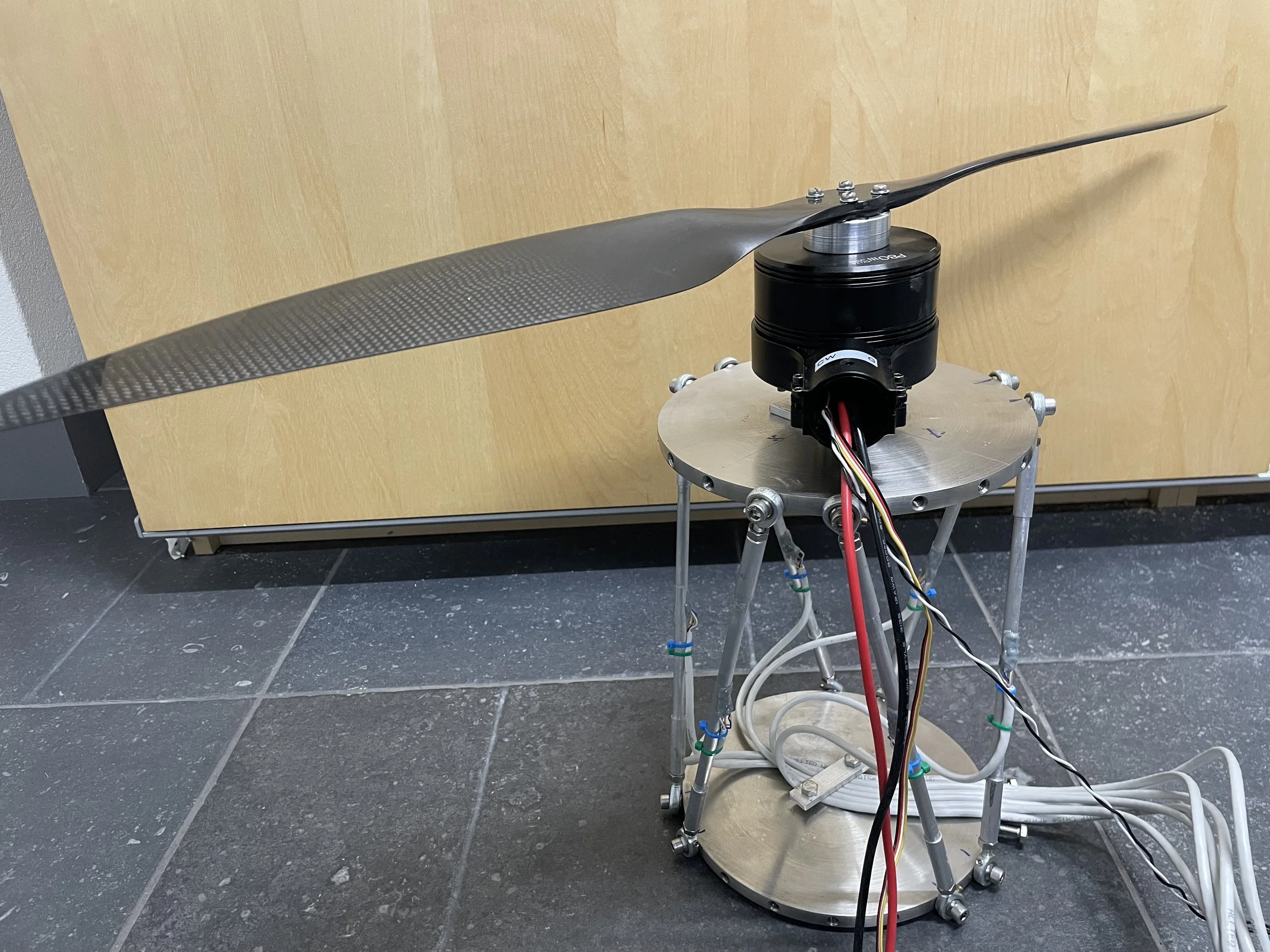
To address the hysteresis issues encountered in previous iterations, I eliminated rod ends entirely in my latest design, opting for a fully rigid structure. This change results in a statically indeterminate system. In simpler terms, even if you remove one rod, the platform remains stable and immovable—an incredibly stiff setup! Some experiments were performed proving that the hysteresis problem is indeed eliminated!
Still a Hexapod?
Does it still qualify as a hexapod? I'm not entirely sure, but it certainly looks like one! More importantly, will it work? While the response may differ from a statically determined system, it's expected that through calibration, a relationship can be established between applied forces and moments and the loads measured by the six load cells. This calibration will depend on ensuring the joints and rods aren't excessively stiff compared to the original statically determined system.
Challenges of the New Approach
This new design effectively resolves the hysteresis problem, but it introduces new challenges. For example, the system now experiences significant preloads, which must be carefully managed to avoid stressing the load cells excessively or outside their operating range.
The Build: Crafting a Stiffer, More Reliable Hexapod
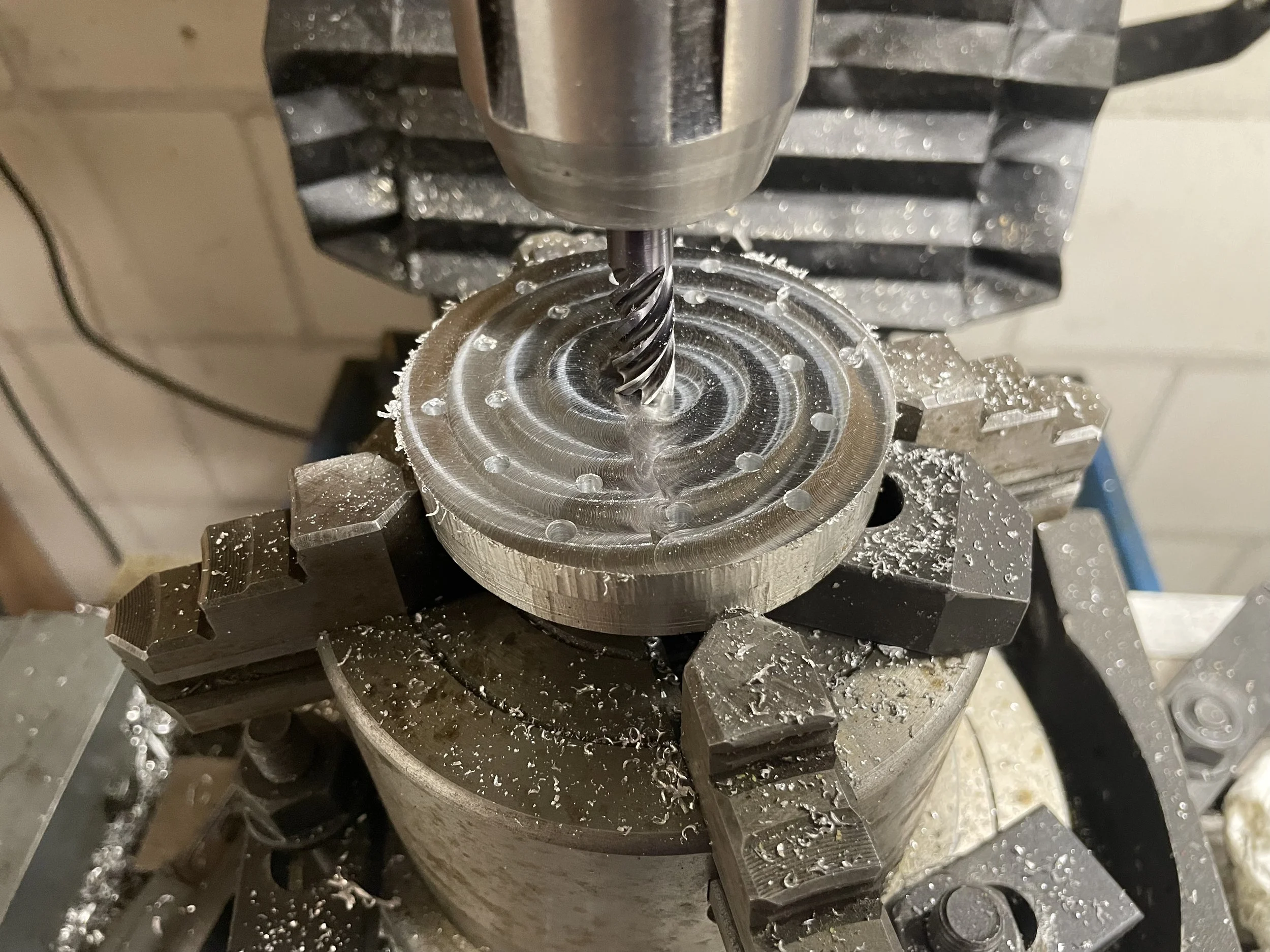
The foundation of the new hexapod design is a thick aluminium disk, carefully machined to mount the six load cells securely. These load cells are bolted down tightly—no movement here! However, there’s a critical insight to keep in mind: due to the statically indeterminate structure and the stiff connections, even a small displacement of a load cell can lead to significant changes in the measurements of all the other load cells. The takeaway? A design like this must be built to ensure absolutely no movement—at least for the duration of the experiment.
Load Cell Mounting
The load cells are fitted with aluminium brackets, each bent into shape to align the threaded rods properly. This “bend-to-shape” approach helps minimize preload in the system, which is crucial for achieving accurate and reliable measurements.
Top Platform Design
The top platform is constructed from a square plate, but the connections are arranged in an equilateral triangle configuration. Stainless steel plates are attached and bent to align precisely with the threaded rods, ensuring consistent geometry across the structure.
A Note on Threaded Rods
In hindsight, the threaded rods should have been significantly thinner. The current design uses 6mm rods, which introduce substantial preload into the system. A quick buckling calculation (and a practical experiment) reveals that a 3mm threaded rod of this length would buckle under approximately 10kg of force—more than sufficient strength for this application (remember there are six rods…). This iteration is a significant step forward, addressing many of the challenges in previous designs while laying the groundwork for further refinements. Stay tuned for what’s next!